
Home |
DynOmics 1.0 |
Tutorials |
Theory |
References |
iGNM 2.0 |
Mol. Sizer&Timer |
ANM 2.0 |
Comp. Biol. Lab |
PITT site
|
|
|
Home |
DynOmics 1.0 |
Tutorials |
Theory |
References |
iGNM 2.0 |
Mol. Sizer&Timer |
ANM 2.0 |
Comp. Biol. Lab |
PITT site
|
Theory
ANM CG-deformation and All-atom Re-construction
One of the most used function of ENM (ANM in this case) is to predict the possible conformations from experimentally solved structures along the slowest ANM modes. The deformed structures (R) can be created by adding sUk [Eq. 8 of the ANM theory] to the atom coordinates (Ro) of x-ray-crystallography- or NMR-solved proteins, where s = RMSD•N1/2 is a scaling factor defined by user-chosen root mean square deviation (RMSD) value, the size of the deformation, and Uk [Eq. 8 of the ANM theory] is the k-th ANM modes. R, Uk and Ro are all arranged as 3N-element vectors where N is the number of CG-nodes (e.g. Ca atoms in proteins) in the system.
Such ANM-guided deformation sometimes can entail, especially when the size of deformation is big, over-stretched (or compressed) pseudo-bonds (connecting two consecutive CG-nodes in the primary sequence) in the deformers. The following algorithm is designed to (A) resolve the overstretched bond lengths between consecutive CG-nodes and (B) reconstruct the all-atom structures from the CG-deformers for the following docking or MD simulation purposes.
The reconstructed fine-grained (all-atom) structures from normal-mode deformed coarse-grained (CG-) structures (CG-deformers) and restoration of bond lengths in the equilibrium state from overstretched or compressed bond lengths between nodes in the CG-deformers take three steps –
(1) Detailed below, general (internal) coordinates are derived from the Cartesian coordinates of the CG-deformers, which are the dihedral angles described by four consecutive CG-nodes, bending angles formed by three consecutive CG-nodes and bond lengths between two consecutive CG-nodes in the primary sequence. Let’s denote the derived set of general coordinates for Ro as F{Ro}. To resolve the overstretching issue, an attachment of the so-called “tip effect”(1), we use the original bond lengths in F{Ro} to replace the bond lengths in F{R} while preserving the dihedral and bond angles in F{R} (the CG-deformer), and then we convert the bond-length-adjusted F{R} back to its corresponding Cartesian coordinates to obtain R’ (Fig. 1). The conversion between Cartesian coordinate system and general coordinate system is described toward the end of the document, according to Flory’s formulation(2).
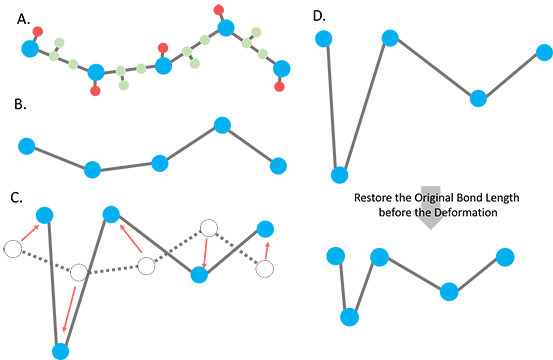
Figure 1. Scheme of the ANM deformation with fixed bond lengths. A.The input all-atom structure. The blue, red and green balls represent the representative nodes (Ca) for a residue, sidechain and backbone atoms, respectively. B. The coarse-grained structure with CG-nodes only. C. The nodes are deformed along the deformation vector sUk with the scaling factor s. The red arrows indicate the direction and scaling of the deformation of nodes. Some of the bond lengths could be overstretched (Ca - Ca distance between neighboring residues > 3.8 Å) in the deformed structure. D. The dihedral angles and bending angles are taken from the newly deformed structure while the bond lengths are restored using the original bond lengths of the input structure.
(2) The backbone atoms between 2 consecutive Ca's (Ci-1 Oi-1 Ni) were rebuilt by superimposing the original structure to the ANM deformed structure with the fixed bond lengths. Every superimposition only includes 3 consecutive Ca's. For every 2 consecutive Ca's (Ca,i-1, Ca,), there are 2 ways perform this superimposition, Ca,i-2, Ca,i-1, Ca,i or Ca,i-1, Ca,i, Ca,i+1. The superimposition with the lowest RMSD was selected. The translation vector and rotation matrix used to do the superimposition were then applied to the backbone atoms between 2 of the Ca's (Ca,i-1, Ca,i). (Fig. 2).
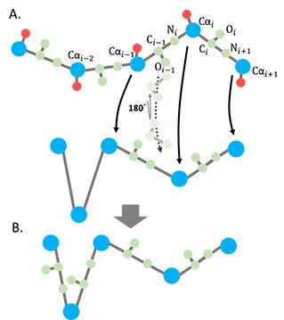
Figure 2. Reconstruction of the backbone atoms for the ANM-deformed coarse-grained structure. A. The backbone assignment for the deformed coarse-grained model. B. The ANM deformed structure with backbone atoms reconstructed.
(3) Finally, side chains are reconstructed by psfgen plugin in VMD (3) and an energy minimization is performed using NAMD (4) with CHARMM36 force field (5) to resolve the possible clash between spatially close atoms to render the final all-atom structure.

Figure 3. The final all-atom structure with reconstructed side chains.
Convert from Cartesian to General coordinates
Let’s define the bond length vectors li, pointing from node i-1 to node i. The following equations are used to transform Cartesian into General coordinates. Bond lengths, bond angles and dihedral angles (see Fig. 4) can be obtained as
![]() (1)
(1)
![]() (2)
(2)
![]()
![]() (3)
(3)
where
nk is the unit normal vector, the normal of the plane spanned
by lk and lk+1, which can be obtained as nk
=(lk ´ lk+1)/|lk
´ lk+1|; “´” is cross product while “![]() ” is inner
product. Sign[x] is the sign (+ or –) of x.
” is inner
product. Sign[x] is the sign (+ or –) of x.
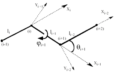
Figure 4. Notations for a chain segment of four bonds used in the general coordinate system. i-1, i, i+1, i+2 are 4 consecutive CG-nodes.
Convert from General to Cartesian coordinates
Using the transformation matrix between frames i+1 and i per Flory’s convention(2), the Cartesian coordinates of the i-th (ri) node at frame i-1 can be expressed as
ri = Ti-1(|li|, 0, 0)’; where ‘ is the transpose, and the transformation matrix T is
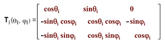 (4)
(4)
Hence the Cartesian coordinates of the ri at frame 2 (the first frame), following a recursive relation, can be expressed as
ri = T2…Ti-2Ti-1(|li|, 0, 0)’ (5)
where frame 2 is spanned by x2 and y2 shown in Figure 5; In this frame, the first node has a coordinate (0, 0, 0) and the second node is at (|l2|, 0, 0).
We can thus obtain the Cartesian coordinates of every CG-node at frame 2 (the first frame).
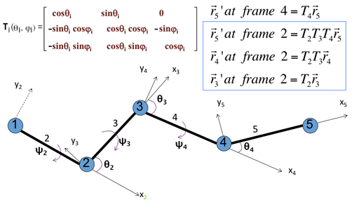
Figure 5. Transformation matrix to express node i +1 in the coordinate frame of node I with examples in the upper-right corner. Coordinates of node 5, r5 = [x5, y5, z5] = [l5, 0, 0] in its own coordinate system; where l5 is the bond length.
References
1. Lu,M. andMa,J. (2011) Normal mode analysis with molecular geometry restraints: Bridging molecular mechanics and elastic models. Arch. Biochem. Biophys., 508, 64–71.
2. Flory,P.J. (1989) Appendix B. In Statistical Mechanics of Chain Molecules. Hanser Gardner Pubns.
3. Humphrey,W., Dalke,A. andSchulten,K. (1996) VMD : Visual Molecular Dynamics. 7855, 33–38.
4. Phillips,J.C., Braun,R., Wang,W., Gumbart,J., Tajkhorshid,E., Villa,E., Chipot,C., Skeel,R.D., Kalé,L. andSchulten,K. (2005) Scalable molecular dynamics with NAMD. J. Comput. Chem., 26, 1781–1802.
5. Vanommeslaeghe,K., Hatcher,E., Acharya,C., Kundu,S., Zhong,S., Shim,J., Darian,E., Guvench,O., Lopes,P., Vorobyov,I., et al. (2010) CHARMM general force field: A force field for drug-like molecules compatible with the CHARMM all-atom additive biological force fields. J. Comput. Chem., 31, 671–690.